ENERGY LINE AND HYDRAULIC GRADE LINE
Energy
Line (EL)
Energy line (EL) shows total head for a certain
cross section in system.
For a fluid flow without any losses due to friction (major losses) or components (minor losses) - the energy line would be at a constant level. In a practical world the energy line decreases along the flow due to loses.
A turbine in the flow reduces the energy line and a pump or fan in the line increases the energy line.
Hydraulic Grade Line (HGL)
Hydraulic Grade Line (HGL) shows piezometric head for a certain cross section in system. The Hydraulic Grade Line is a line representing the total head available to the fluid - minus the velocity head and can be expressed as:
The Hydraulic Grade Line lies one velocity head below the energy line.
Example of Energy Line (EL) and Hydraulic Grade Line (HGL)
Example 1
Example 2
Example 3
Example 4
Example 5
Conclusion
- Energy Line always higher or same level
with Hydraulic Grade Line.
- The difference between 2 line is the
values of kinetic energy head,
- Major losses – cause Energy Line and
Hydraulic Grade Line to decrease gradually
- Minor losses – cause Energy Line and Hydraulic Grade Line to
decrease rapidly.
- Use of pump – Lines increased immediately
- Use of turbine – Lines decrease immediately
FLOW TO ATMOSPHERE
Flow To Atmosphere
Energy equation from A to B
Example of Flow To Atmosphere
FLOW CONNECTING 2 RESERVOIRS
FLOW WHICH CONNECTING 2 RESERVOIRS
FIGURE 01
EXAMPLES :
The pipe diameter is 100mm and has length 15m and feeds directly into the atmosphere at point C 4m
below the surface of the reservoir (i.e. za – zc = 4.0m). The highest point on the pipe is a B which is 1.5m above the surface of the reservoir (i.e. zb – za = 1.5m) and 5 m along the pipe measured from the reservoir. Assume the entrance and exit to the pipe to be sharp and the value of friction factor f to be 0.08.
Calculate
a) velocity of water leaving the pipe at point C,
b) pressure in the pipe at point B.
SOLUTION
a) We use the Bernoulli equation with appropriate losses from point A to C and for entry loss kL = 0.5 and exit loss kL = 1.0.
For the local losses from Table 2 for a sharp entry kL = 0.5 and for the sharp exit as it opens in to the
atmosphere with no contraction there are no losses, so
Friction losses are given by the Darcy equation
Pressure at A and C are both atmospheric, uA is very small so can be set to zero, giving
Substitute in the numbers from the question
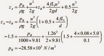
b) To find the pressure at B apply Bernoulli from point A to B using the velocity calculated above. The length of the pipe is L1 = 5m:
That is 28.58 kN/m2 below atmospheric.
by : AmiraHaris
NON - VIGOROUS HEADLOSS EQUATION
The empirical equation which are Hazen-William, Manning and Darcy Weisbach were arranged into the form of head loss equation
Darcy Weisbach
Darcy–Weisbach equation is a phenomenological equation, which relates the head loss — or pressure loss due to friction along a given length of pipe to the average velocity of the fluid flow. The equation is named after Henry Darcy and Julius Weisbach
The Darcy-Weisbach equation is valid for fully developed, steady state and incompressible flow. The friction factor or coefficient, λ -depends on the flow, if it is laminar or turbulent (the Reynolds Number) - and the roughness of the tube or duct. The friction coefficient can be calculated by using the Moody Diagram.
For this, it is necessary to substitute the following into the original head loss form of the Darcy–Weisbach equation

where
For the general case of an arbitrarily-full pipe, the value of Aw will not be immediately known, being an implicit function of pipe slope, cross-sectional shape, flow rate and other variables. If, however, the pipe is assumed to be full flowing and of circular cross-section, as is common in practical scenarios, then

By substituting the original formulation yields the final equation for head loss in terms of volumetric flow rate in a full-flowing circular pipe. The equation below are defined.
Hazen - William
Hazen–Williams equation is an empirical relationship which relates the flow of water in a pipe with the physical properties of the pipe and the pressure drop caused by friction. It is used in the design of water pipe systems such as fire sprinkle systems, water supply networks, and irrigation systems. It is named after Allen Hazen and Gardner Stewart Williams.
The Hazen–Williams equation has the advantage that the coefficient C is not a function of the Reynold's Number, but it has the disadvantage that it is only valid for water. Also, it does not account for the temperature or viscosity of the water
The Darcy-Weisbach equation was difficult to use because the friction factor was difficult to estimate.The general form of the equation relates the mean velocity of water in a pipe with the geometric properties of the pipe and slope of the energy line.
- V is velocity
- k is a conversion factor for the unit system (k = 1.318 for US customary units, k = 0.849 for SI units)
- C is a roughness coefficient
- R is the hydraulic radius
- S is the slope of the energy line head loss per length of pipe or hf/L
When used to calculate the head loss with the International System of Units, the equation becomes
Manning
Manning formula is also known as the Gauckler-Manning Formula or Gauckler–Manning–Strickler formula in Europe. In the United States, in practice, it is very frequently called simply Manning's Equation. The Manning formula is an empirical formula estimating the average velocity of a liquid flowing in a conduit that does not completely enclose the liquid. All flow in so-called open channels is driven by gravity. It was first presented by the French engineer Philippe Gauckler in 1867, and later re-developed by the Irish engineer Robert Manning.
The Gauckler–Manning formula states:

where:
- V is the cross-sectional average velocity (L/T; ft/s, m/s);
- n is the Gauckler–Manning coefficient. Units for values of n are often left off, however it is not dimensionless, having units of: (T/[L1/3]; s/[ft1/3]; s/[m1/3]).
- Rh is the hydraulic radius (L; ft, m);
- S is the slope of the hydraulic grade line or the linear hydraulic head loss (L/L), which is the same as the channel bed slope when the water depth is constant. (S = hf/L).
- k is a conversion factor between SI and English units. It can be left out if consistent units are used throughout. However it is standard practice to use k=1 for SI units, and k=1.49 for English units. (Note: (1 m)1/3/s = (3.2808399 ft) 1/3/s = 1.4859 ft1/3/s)
NOTE: Ks strickler = 1/n manning. The coefficient Ks strickler varies from 20 (rough stone and rough surface) to 80 m1/3/s (smooth concrete and cast iron).
The discharge formula, Q = A V, can be used to manipulate Gauckler–Manning's equation by substitution for V. Solving for Q then allows an estimate of the volumetric flow rate(discharge) without knowing the limiting or actual flow velocity.
The equation then now is being used as a Manning headloss equation,
by : AmiraHaris
FLOW THROUGH BRANCHES PIPES
When three or more reservoirs are connected by
means of pipes, having one or more junctions, then this arrangement is callled
branching of pipe.
In several practical situations, flow takes place under a given head
through different pipes jointed together either in series or in parallel or in
a combination of both of them.
We shall assume that all the pipesare sufficient
long that we canneglect minor losses and velocityhead so h
hL= hf which we
shalldesignate as h.
As there are no pumps, the elevation of P must
liebetween the surfaces of reservoirs A and C.If P is below the surface of
reservoir Bthen h2 and Q2
are both zero.If P is above the surface of
reservoir B then watermust flow into B and Q1 = Q2 +Q3
.If P is below the surface of reservoir B then
watermust be out of B and Q1
+Q2 = Q3.There are several
different method of solutions.
Example:
The elevations of water surfaces in reservoirs A
andC are 250 ft and 160 ft, respectively and thedischarge Q2 into
reservoir B is 3.3 cfs. Find thesurface elevation of reservoir B.
PIPE IN SERIES
If a pipeline is joined to one or more pipelines in
continuation, these are said to constitute pipes in series. A typical example
of pipes in series is shown in Fig. 36.1. Here three pipes A, Band C are joined in series.
In this case, rate of flow Q remains same in each
pipe. Hence,
QA = QB = QC = Q
If the total head available at Sec. 1 (at the inlet
to pipe A) is which is H1 greater than H2, the total head
at Sec. 2 (at the exit of pipe C), then the flow takes place from 1 to 2
through the system of pipelines in series.
Application of Bernoulli's equation between Secs.1
and 2 gives
The subscripts A, B and C efer
to the quantities in pipe A, B and C respectively. Cc is the coefficient of
contraction.
The flow rate Q satisfies the equation:
PIPES IN PARALLEL
When two or more pipes are connected, so that the flow divides subsequently comes together again, the pipes are said to be in parellel.
In this case, equation of continuity gives
Q= QA +QB
where, Q is the total flow rate and QA and QB are the flow rates through pipes A and B respectively.
Loss of head between the locations 1 and 2 can be expressed bby applying Bernoulli's equation either through the path 1-A-2 or 1-B-2.
Therefore, we can write
From the above discussion on flow through branched pipes (pipes in series or in parallel, or in combination of both), the following principles can be summarized.
- The friction equation must be satisfied for each pipe.
- There can be only one value of head at any point.
- Algebraic sum of the flow rates at any junction must be zero. i.e., the total mass flow rate towards thee junction must be equal to the total mass flow rate away from it.
- Algebraic sum of the products of the flux (Q^2) and the flow resistance ( thee sense being determined by the direction of flow) must be zero in any closed hydraulic circuit.
The principles 3 and 4 can be written analytically as
While Eq. 3.69 implies the principle of continuity in a hydraulic circuit. Eq 36.10 is referred to as pressure equation of the circuit.
Past